Structure Analysis Lab
The primary objective of the Structure Analysis Lab is to advance the understanding of structural behavior and performance, and develop innovative solutions for designing safe, efficient, and sustainable structures. The lab provides a collaborative and interdisciplinary research environment, bringing together experts from civil engineering, materials science, computer science, and other related fields to conduct research on a wide range of topics in structural engineering.
 Subhamoy Sen
 J Dhanya
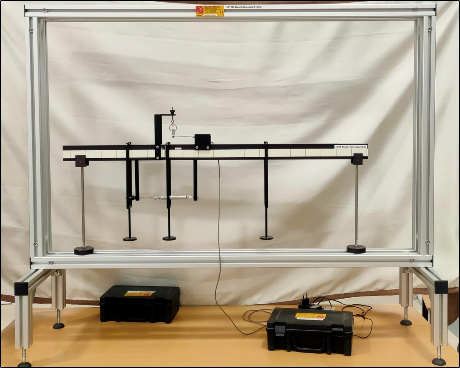
HST 9 Shear Force Apparatus
To determine the shear force in a beam.
Each beam is simply supported on vertical supports which can be easily moved to create varying beam spans. At the ‘cut’ section, bearings in one beam straddle a vertical bearing track in the mating beam. This ensures free vertical movement for monitoring shear forces. Although beam bending is permitted, it is counteracted by the bearings and a tension spring supported horizontally from underneath the beams.
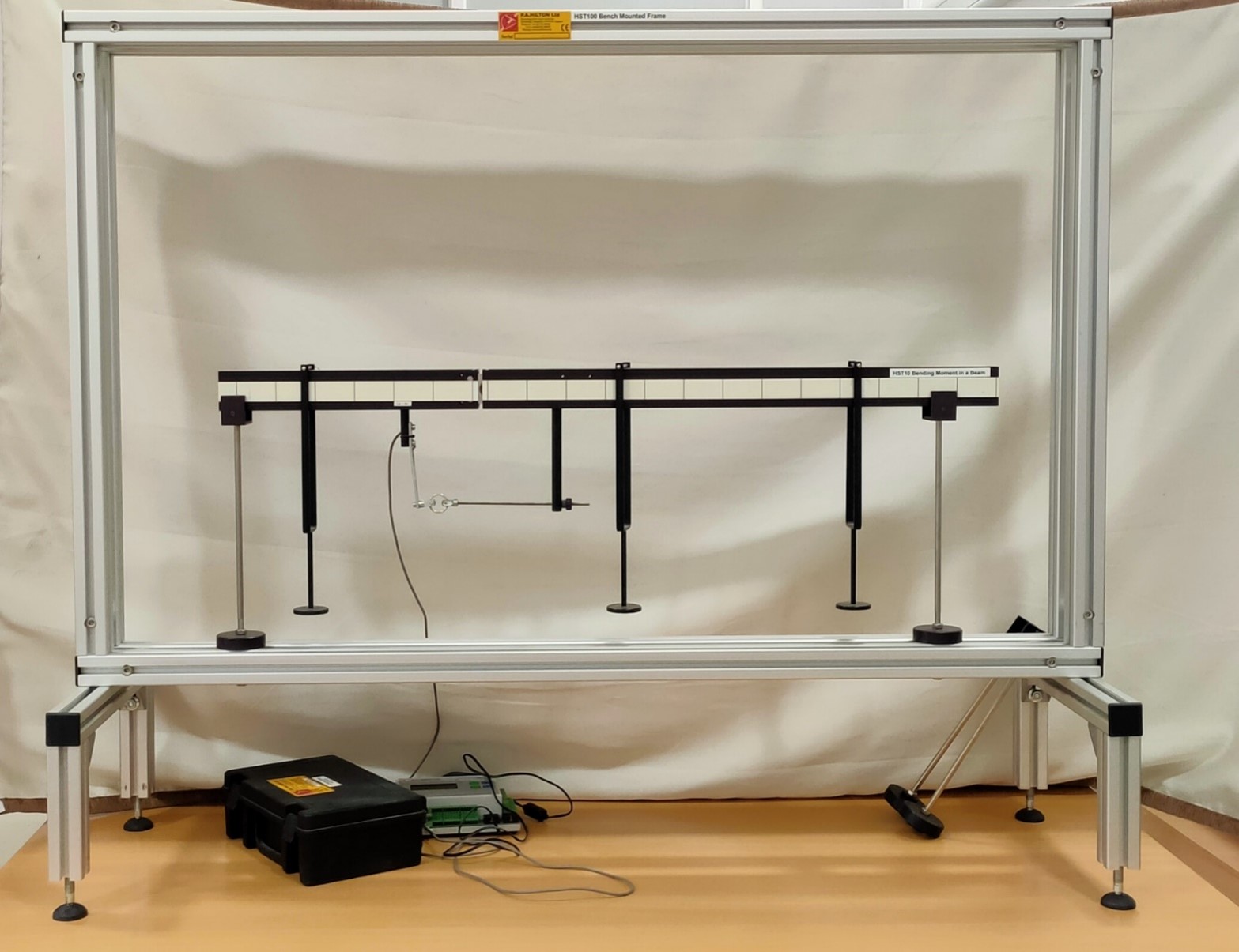
HST 10 Bending Moment
To determine the bending moment in beam.
Each beam is simply supported on vertical supports which can be positioned in a variety of positions along the beam lengths. At the ‘cut’ section, a bearing in one beam rests inside a radiused pocket of the other beam. This restricts any vertical movement between the two beams (hence removes any visible shear force), but does not restrict rotation between the two beams and hence bending is not restricted.
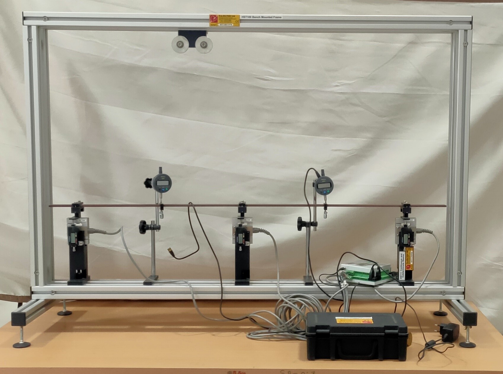
HST 11 Continuous and intermediate Beam
To determine the deflection in the beam.
Three piers measure vertical reaction forces with their integral load cell which connect directly to the HDA200 Interface (sold separately). Each pier caters for simply supported, or continuous beams and their beam attachments allow for rotation but no vertical movement during testing.
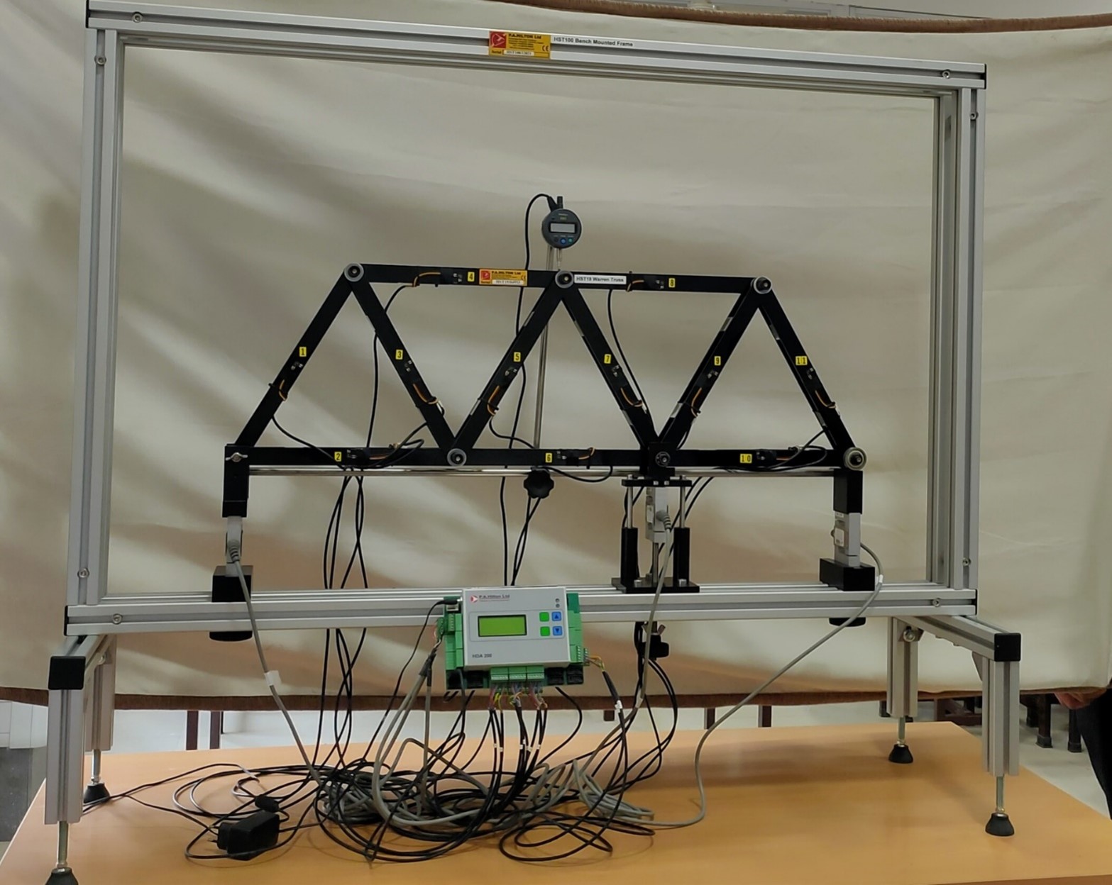
HST 19 Truss
To determine the deflection in different members of truss.
Two assembled pin-jointed frameworks (warren and basic roof truss) to measure the strains (hence stresses) and joint deflections. Each member, when assembled creates a truly pin joint. The frameworks mount onto two end supports. One support has a pivoting arrangement whilst the other has pivoting and rolling arrangement. The loads on the framework are applied at specific joints by using the screw-jack loading mechanism supplied. Each framework member has a strain gauge arrangement attached.
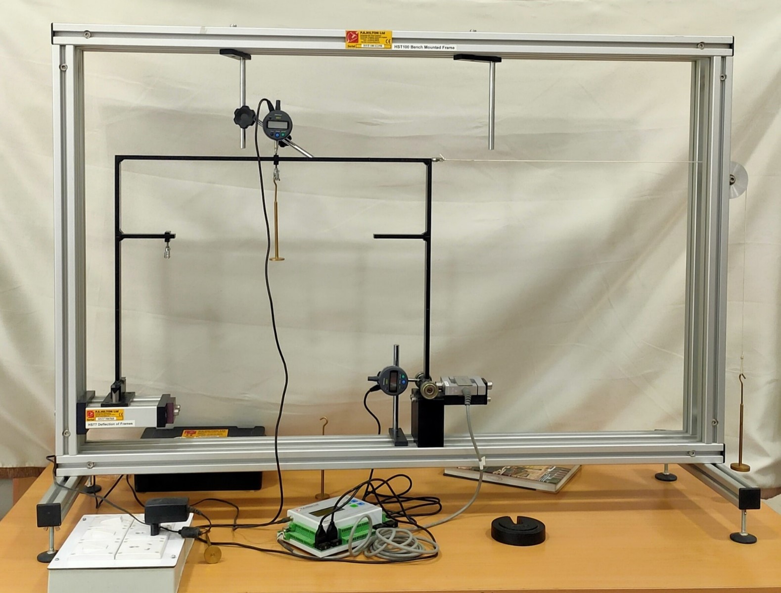
HST 7 Deflection In Frames
To determine the deflection in frames.
A 'rectangular' Portal frame made from rectangular solid steel section are provided with either pinned ends or simple supports to enable each frame to be set up in the HST1 Universal Frame and Stand (sold separately) and loaded horizontally and vertically. One end of the portal frame pivots on a knife edge, while the other end is free to move horizontally on a track plate against a load cell.
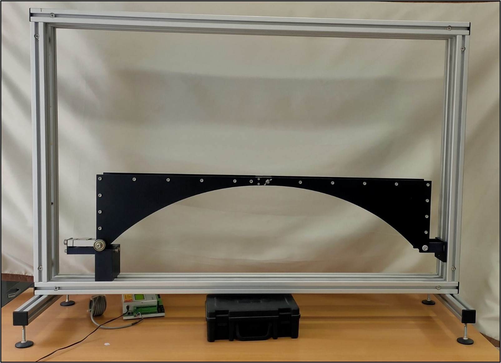
HST 4 Three Hinge Arch
To determine the horizontal thrust on arch.
One meter flat bridge deck is formed using two symmetrical arches. The arches have springing's (hinges) at their outer most ends and at the crown (center), thus creating the three hinges. The left hand springing is held in position whilst allowing rotational movement of the arch section. The right hand springing allows the arch section to rotate and move horizontally against a load cell on a track plate.